Ic 7483 Pin Diagram Circuit Design And Implementation Of A B
Circuit diagram for 4 bit binary adder using ic 7483 Solved 2. design an adder/subtractor circuit using 7483 and Bcd subtractor using ic 7483 circuit diagram
Circuit Diagram For 4 Bit Binary Adder Using Ic 7483 » Diagram Board
The counting thread [diagram] logic diagram of ic 7483 Ic 7483 internal circuit diagram
Design and implementation of 10’s complement circuit using ic-7483
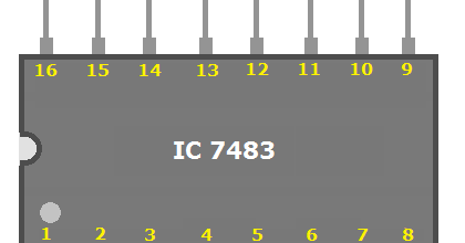
Circuit diagram for 4 bit binary adder using ic 7483Ic 7446 datasheet pdf 74hc83 full adder ic pinout, datasheet, equivalent working, 50% offIc 7483 pin diagram, truth table, applications.
Ic 7483 pin diagram circuitIc 7483 internal circuit diagram Ic 7483 pin diagram circuit#4bit_binary_adder_(design, implement and verify the truth table using.
![Design And Implementation of a BCD Adder Circuit Using IC-7483](https://i2.wp.com/circuitdiagrams.in/wp-content/uploads/2022/04/IMG-20220418-WA0002.jpg)
Four bit adder or subtractor using 7483
Ic 7483 internal circuit diagramDigital electronics: 4 bit magnitude comparator ic (7485) 7483 4-bit binary full adder icDesign and implement 9's complement circuit using ic-7483.
7486 ic quad 2-input exclusive-or gateDesign and implementation of 10’s complement circuit using ic-7483 Circuit diagram for 4 bit binary adder using ic 7483 » diagram board74ls48 bcd-to-7 segment decoder/driver ic in pakistan.
![Ic 7483 Pin Diagram Circuit](https://3.bp.blogspot.com/-4e2Z1Pi50u0/UC4ZXx-uPAI/AAAAAAAAAqU/yMn4t3zSw4k/s1600/logicdiagramforbcdadder.bmp)
7486 ic logic xor ttl gate input quad exclusive family partco dip14 datasheet hc electronics fi
7485 comparator ic bit magnitude electronics digitalDesign and implementation of a bcd adder circuit using ic-7483 12+ ic 7420 pin diagramCircuit diagram for 4 bit binary adder using ic 7483.
.
![(Solved) - The 4 bit adder/subtractor circuit implemented with IC 7483](https://i2.wp.com/files.transtutors.com/book/qimg/90023872-a4e4-42ab-86ef-ffb1830ef8ba.png)
![IC 7446 DATASHEET PDF](https://i2.wp.com/www.futurlec.com/DIP16.gif)
![The Counting Thread - v2 (Page 250) - EVGA Forums](https://1.bp.blogspot.com/-H77EW09ehpc/XbmwBmW5QuI/AAAAAAAACTg/gj7qFK2Xzw4RFJUN19VLIfxJY6HnRWnUQCLcBGAsYHQ/w1200-h630-p-k-no-nu/IC%2B7483%2BPin%2BDiagram.png)
![Four Bit Adder or Subtractor using 7483 - EEES.IN](https://i2.wp.com/eees.in/wp-content/uploads/2021/10/image-58.png)
![#4bit_binary_adder_(Design, implement and verify the truth table using](https://i.ytimg.com/vi/96PoxSukE0I/maxresdefault.jpg)
![74HC83 Full Adder IC Pinout, Datasheet, Equivalent Working, 50% OFF](https://i2.wp.com/components101.com/sites/default/files/component_pin/74LS83-pin-diagram.png)
![Circuit Diagram For 4 Bit Binary Adder Using Ic 7483 » Diagram Board](https://i2.wp.com/holooly.com/wp-content/uploads/2021/07/16.5-1.png?strip=all)
![7483 4-bit Binary Full Adder IC - Electronic Components & Robotics](https://i2.wp.com/1ohm.in/wp-content/uploads/2021/07/7483-IC-Pinout.jpg)
![Ic 7483 Pin Diagram Circuit](https://i.pinimg.com/736x/53/e0/ed/53e0ed6a4fc95fbf2cbc24f1d116cab0.jpg)
![Design and Implementation of 10’s Complement Circuit Using IC-7483](https://i2.wp.com/circuitdiagrams.in/wp-content/uploads/2022/04/10s-Complement-Circuit-Diagram-1536x1072.png)